This article is the part of “The most hacked router in the world ever” project documentation.
This hack is very popular, you can find it published on many websites and all descriptions are the same: shortcut 4-5 and 7-8 pairs, send power using them through your ethernet cable and be safe because your router doesn’t use those pairs. IT DOES!! So if you’re implementing one of those hacks stop it now and keep reading.
First of all please understand that all those “POE” hacks (including this one) have nothing common with real Power Over Ethernet protocol. Real POE is a family of protocols that have couple proprietary incompatible implementations and while being not too sophisticated it is not trivial as well. You can read more about it here in wikipedia. That means if you try plugging your modded Linksys to a real POE equipment there is a good change you will deep fry something. So make sure you don’t mix this fake “POE” with real one.
 I implemented this hack as it was described first, but fortunately was extra careful and initially fed only 3.3V to see what will happen. To my surprise I notice nonzero voltage not only on 4-5 and 7-8, but all other pins as well. I checked this with WRT54GL with the same result. Those pins aren’t disconnected, they somehow connected to the guts and applying power to them is not safe at all. I’m not an EE expert, so can’t tell you exactly why they are not just abandoned. My version is that they are hooked up to couple resistors to implement part of the real POE. According to wikipedia “A PD indicates that it is standards-compliant by placing a 25 kΩ resistor between the powered pairs” and that looks like what is implemented in Linksys.
If you take a look at the photo showing wires connected to the RJ45 socket pins you will clearly see why it is so easy to mistakenly assume that Linksys uses only two pairs in ethernet cable. However if you’re curious enough and have an ohmmeter you can easily find out that the other two pairs are used too and the PCB is double-sided.
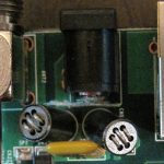
 I’m not sure how the traditional POE hack is working with other routers, but it could work on older models that really don’t use those two pairs. Or Linksys routers are just built with modders in mind so 5V applied to wrong place don’t kill it. I needed to feed 12V though (the fan runs@12V and I didn’t want to embed step-up DC-DC converter to preserve space) and decided to spend some time and cut those lines off. The easiest way to do that is lifting two resistors as shown on the picture. I kept the resistors in place so I can reverse the hack, but it is easier to remove them completely.
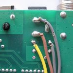 The other part of the hack is keeping your equipment safe when it is accidentally plugged to both power sources. Some people recommend using a rectifier diode. I decided to use simple DPDT switch, so only one source of power can be in use. You can probably use SPDT for simplicity, but cutting off the grounds looks safer. If you go this way you will also need to cut the DC connector from the rest of the board by cutting traces near it on the top side as shown on this really bad photo.
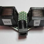
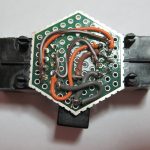 The final part of this hack is the injector. You can buy one, but I happened to have necessary parts to build my own. Here is the parts list:
- 2x RJ45 – use the cheapest ones, you don’t need magnetics here.
- 1x DC connector – choose the one that fits your power supply. This one works with the standard Linksys supply.
- 1x hex-shaped proto board – to my surprise it perfectly fits the RJ45 pins. Sparkfun also has breakout boards for RJ45s, but they don’t work as well.
I’d also would like to recommend SparkFun Electronics as one of the best parts suppliers. Their prices are not the lowers ones, but if you think that your time is money you will definitely save some by using SparkFun’s website rather then cheaper DigiKey or Mouser. They also publish very interesting projects on their website and overall leave impression of good guys :) So I highly recommend visiting their website periodically. Most parts for this project came from SFE.
PS. I can’t say for all Linksys routers, but all routers I saw can be powered either from 5V2A or 12V1A power supplies. It has pair of embedded buck regulators right after the power input and the regulators are rated up to 22V. So I cannot guarantee that you can apply that high voltage, but this is some info to keep in mind :)